By Dean Ketelsen, Member
While being able to track stars accurately may seem a daunting challenge, it is really quite easy, as long as we are talking about wide angle to slight telephoto camera lenses. More powerful lenses (greater than 180mm) are probably best left for equatorial mounts, real worm gears, and likely a guide scope. The barn door mount I built took only a few hours of effort and cost only a few dollars over the tripod and camera ball mount I already had.
There are several designs out there – the one I made is called a curved sector drive, because the threaded rod it uses is curved. You can use a straight tangent drive, but the drive screw should be turned at different rates depending on where it is along the tangent drive. The curved sector drive uses a constant drive rate so is simpler from that aspect. The only complication is that the curve needs to be pretty well matched to the distance from the hinge.
Initial Calculations
To get started, I needed to figure out the distance from hinge to sector drive. I wanted to use threaded rod – 1/4″X20 threads per inch (tpi). Two feet of it at Ace hardware was only $.75! I also wanted to turn the drive nut once per minute, so I needed to calculate how big would a worm gear be that had 20 tpi and a drive that rotated once per minute. In a sidereal day (length of time it takes the stars to circle the sky once) there are 23h56m, 1436 minutes in all, or 1436 teeth in our imaginary gear. At 20 tpi, that would make a circle of 71.8″ circumference, or 22.855″ diameter. If our barn door was half that, or 11.43″ between our 1/4″X20 drive and the hinge and the drive nut was turned once per minute, it would precisely track the stars! You can make a similar calculation if you chose a threaded rod with more or less teeth. If you chose a 1/4″X28 threaded rod (standard fine thread for 1/4 inch size), you could make a more compact barn door mount as you would only need 8.16″ between hinge and drive. In any case, I used 1/4″X20 and got great results.
Tracking Issues
The next task was to bend the threaded rod to match the 11.43″ radius so that the mount would track correctly and there would not be a lot of drag as the barn door mount was rotated about it’s hinge. Because the rod is so springy, you need to bend it around a form that is significantly smaller than 11.43″ radius. I happened to have a piece of aluminum irrigation tubing scrap from a telescope tube that was 12″ diameter and it turns out that was just about perfect for bending to the radius I needed. I first used a compass to make a circle that was the desired 11.43″ radius, then took several tries to match the rod to it. Eventually, with a little touchup bending, it fit as perfectly as I could make it without any tools.
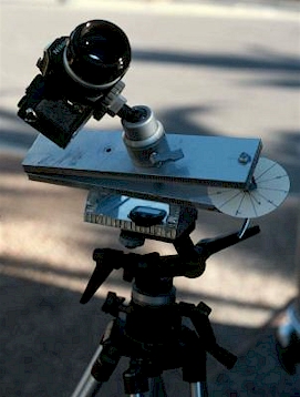
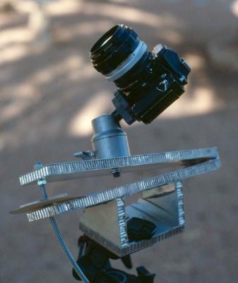
Check out the photos of my barn door mount. I happened to have some lightweight aluminum structural material which is easy to work, but I could have used some 1/2″ plywood with good effect as well. You need to get a hinge that has very little play and the best I’ve found are the piano hinges that you can get up to several feet long. They are quite rigid and yet rotate freely. I bought a 12″ version and cut it down to about 3″ wide for my mount, but in hindsight, I should have gone wider to at least 6″ for increased rigidity. The 3″ section of hinge is barely adequate for my purpose here. In addition, if you make a wider barn door you could mount multiple cameras on it for meteor showers! The pictures show how I made the mount with the hinge on one side and holes for the curved drive on the other, with that spacing of 11.43″ held carefully. You have the option of lowering the upper movable part of the mount if you put the sector drive on the west side, or like I did, raise the upper part of the mount with it on the east side. You need to have some way to hold the mount to the angle to match your latitude, in our case about 32 degrees. I chose to keep the tripod head level for maximum stability and built in a tilted bracket to get my 32 degree adjustment. Fasten it to your tripod, adapt your camera to the upper plate and you are about ready to go. I already had the ball camera bracket, but you can similarly go to a camera store (the Jones Photo Pro Division on Country Club has a huge variety of camera mounts and tripod heads) and get an equivalent. Similarly, if you have TWO tripods, you can take the head off one of them to use as the camera mount on the barn door.
For the drive, I glued a long narrow piece of plastic to a 1/4X20 nut so that I could turn the nut accurately during the long exposures. In practice, imagine that it is the sweep second hand of a clock and that is the speed that you need to turn it. I chose not to complicate things by trying to motorize it, but it could easily be done. If you have a timer of some sort and a scale mounted to the bottom plate near the drive nut, you can easily move it accurately enough for a 135mm lens. A small red flashlight helps to see what you are doing. Think of it this way – in my “rules of thumb” I told you about the longest exposure you could take with a camera lens before it showed trailing was 650/lens focal length. So for a 50mm camera lens, you can go for a 13 second exposure before it shows trails. Now use this as a guide to how accurately you need to turn your drive nut on the barn door mount. At 13 seconds before trailing shows, you could make an adjustment every 10 seconds and no trailing would result. Similarly, for a 135 lens, your “window” is about 5 seconds, so you must be on the ball when tracking the longer focal lengths. I went with a 135mm lens for 10 minutes, so it can be done even manually turning the drive nut with good results.
As for alignment on the pole, you can go to a lot of work to put in some sort of pointer, but any error in installing it relative to the rotational axis of the hinge adds to the overall pointing error. I just sight up along the hinge to Polaris, and even with my short 3″ long hinge, it seems accurate enough. A longer hinge as I suggested would make a more accurate sight.
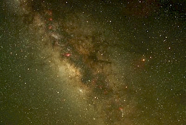
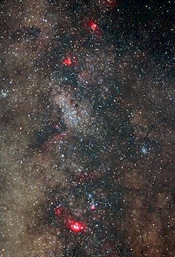
That’s about it – check out the photos to see some pretty good results. E-mail me if you have any questions at ketelsen at as.arizona.edu.